
FEATURE
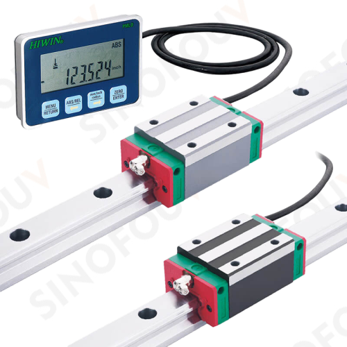
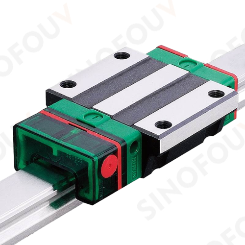
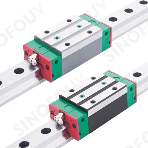
APPLICATIONSSemiconductor equipments、PCB assembly equipments、Medical equipments、Robots、Precision measuring equipments、Office automation equipments、Other miniature sliding mechanism |


| Model | Dimensions of Assembly(mm) | Dimensions of Block(mm) | Dimensions of Rail(mm) | Basic Dynamic Load Rating | Basic Static Load Rating | Weight | ||||||||||||||||||||||
|---|---|---|---|---|---|---|---|---|---|---|---|---|---|---|---|---|---|---|---|---|---|---|---|---|---|---|---|---|
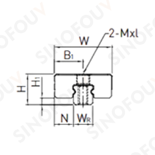
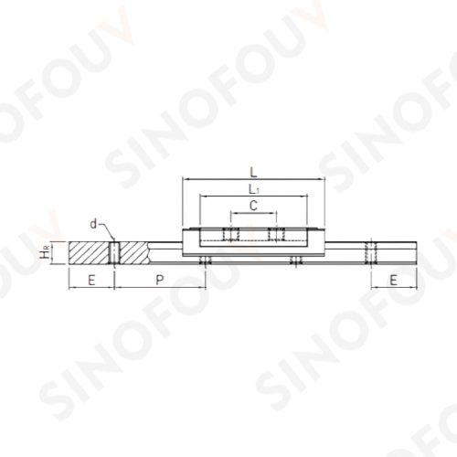
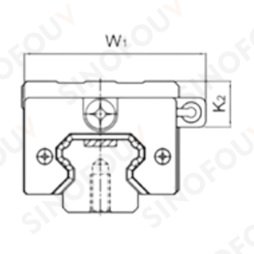
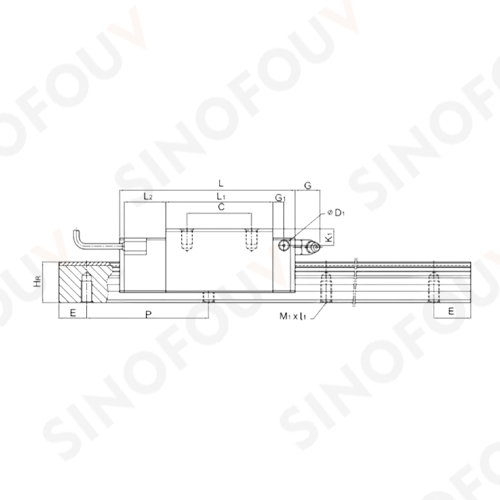
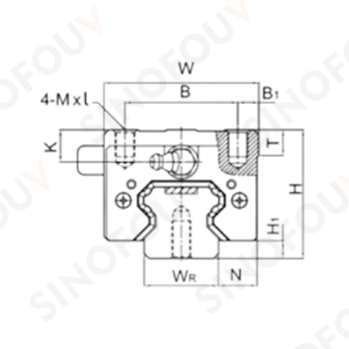
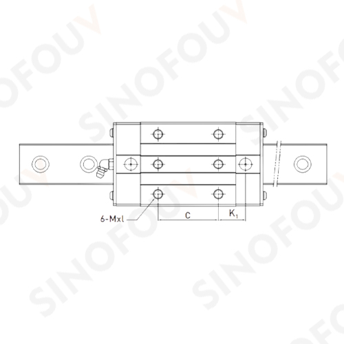
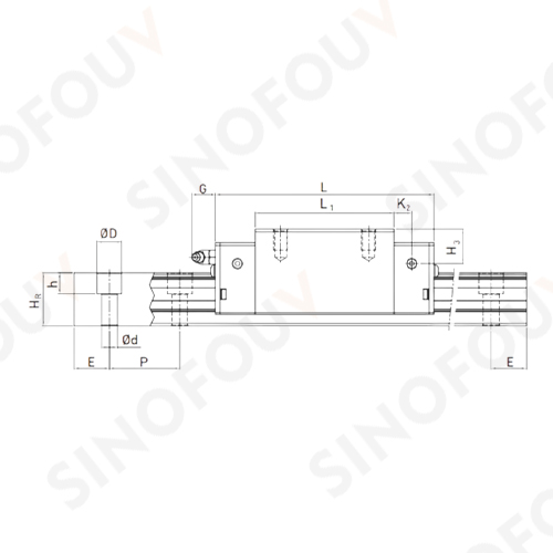
| H | H1 | N | W | W1 | B | B1 | C | L | L1 | L2 | G | G1 | D1 | K | K1 | K2 | Mxl | T | WR | HR | M1xl1 | P | E | C(kN) | C0(kN) | Block(kg) | Rail(kg/m) | |
| PGHH20CA | 30 | 4.6 | 12 | 44 | 52 | 32 | 6 | 36 | 90.5 | 50.5 | 25 | 12 | 6 | 5 | 6 | 6 | 10 | M5x6 | 8 | 20 | 17.5 | M6x10 | 60 | 20 | 27.1 | 36.68 | 0.38 | 2.05 |
| PGHH20HA | 30 | 4.6 | 12 | 44 | 52 | 32 | 6 | 50 | 105.2 | 65.2 | 25 | 12 | 6 | 5 | 6 | 6 | 10 | M5x6 | 8 | 20 | 17.5 | M6x10 | 60 | 20 | 32.7 | 47.96 | 0.39 | 2.05 |
| PGHH25CA | 40 | 5.5 | 12.5 | 48 | 55.4 | 35 | 6.5 | 35 | 95 | 58 | 22.5 | 12 | 6 | 5 | 10 | 9 | 14 | M6x8 | 8 | 23 | 22 | M6x12 | 60 | 20 | 34.9 | 52.82 | 0.51 | 3.05 |
| PGHH25HA | 40 | 5.5 | 12.5 | 48 | 55.4 | 35 | 6.5 | 50 | 116 | 78.6 | 22.5 | 12 | 6 | 5 | 10 | 9 | 14 | M6x8 | 8 | 23 | 22 | M6x12 | 60 | 20 | 42.2 | 69.07 | 0.69 | 3.05 |
| PGHH30CA | 45 | 6 | 16 | 60 | 67 | 40 | 10 | 40 | 110 | 70 | 23 | 12 | 6 | 5 | 9.5 | 13.8 | 19 | M8x10 | 8.5 | 28 | 26 | M8x15 | 80 | 20 | 48.5 | 71.87 | 0.88 | 4.31 |
| PGHH30HA | 45 | 6 | 16 | 60 | 67 | 40 | 10 | 60 | 133 | 93 | 23 | 12 | 6 | 5 | 9.5 | 13.8 | 19 | M8x10 | 8.5 | 28 | 26 | M8x15 | 80 | 20 | 58.6 | 93.99 | 1.16 | 4.31 |
| PGHH35CA | 55 | 7.5 | 18 | 70 | 77 | 50 | 10 | 50 | 123 | 80 | 23.4 | 12 | 7 | 5 | 16 | 19.6 | 23.5 | M8x12 | 10.2 | 34 | 29 | M8x17 | 80 | 20 | 64.6 | 93.88 | 1.45 | 6.14 |
| PGHH35HA | 55 | 7.5 | 18 | 70 | 77 | 50 | 10 | 72 | 148.8 | 105.8 | 23.4 | 12 | 7 | 5 | 16 | 19.6 | 23.5 | M8x12 | 10.2 | 34 | 29 | M8x17 | 80 | 20 | 77.9 | 122.77 | 1.92 | 6.14 |
| PGHH45CA | 70 | 9.5 | 20.5 | 86 | 91 | 60 | 13 | 60 | 148 | 97 | 24.5 | 12.9 | 10 | 8.5 | 18.5 | 30.5 | 30.5 | M10x17 | 16 | 45 | 38 | M12x24 | 105 | 22.5 | 103.8 | 146.71 | 2.73 | 10.25 |
| PGHH45HA | 70 | 9.5 | 20.5 | 86 | 91 | 60 | 13 | 80 | 179.8 | 128.8 | 24.5 | 12.9 | 10 | 8.5 | 18.5 | 30.5 | 30.5 | M10x17 | 16 | 45 | 38 | M12x24 | 105 | 22.5 | 125.3 | 191.85 | 3.61 | 10.25 |
| PGHH55CA | 80 | 13 | 23.5 | 100 | 106 | 75 | 12.5 | 75 | 172.7 | 117.7 | 26 | 12.9 | 11 | 8.5 | 22 | 29 | 28.5 | M12x18 | 17.5 | 53 | 44 | M14x25 | 120 | 30 | 153.2 | 211.23 | 4.17 | 14.92 |
| PGHH55HA | 80 | 13 | 23.5 | 100 | 106 | 75 | 12.5 | 95 | 210.8 | 155.8 | 26 | 12.9 | 11 | 8.5 | 22 | 29 | 28.5 | M12x18 | 17.5 | 53 | 44 | M14x25 | 120 | 30 | 184.9 | 276.23 | 5.49 | 14.92 |
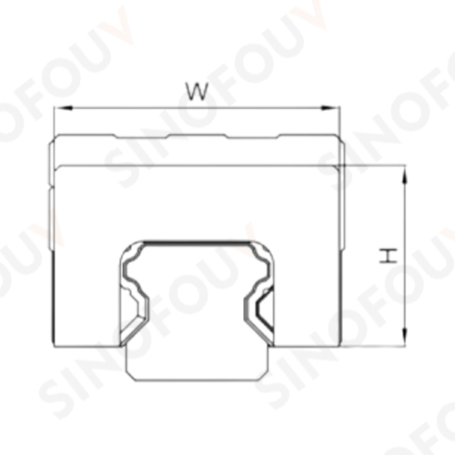
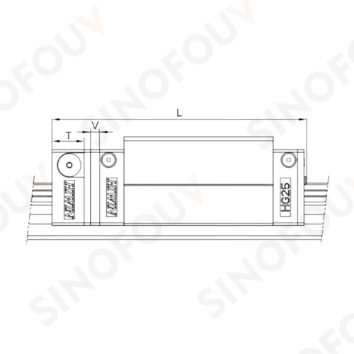
| Model | E2 self-lubrucatung module dimensions | |||||||
|---|---|---|---|---|---|---|---|---|
| W | H | T | V | L | ||||
| SS | ZZ | DD | KK | |||||
| HG15C | 32.4 | 19.5 | 12.5 | 3 | 75.4 (75.6) | 82.5 (82.7) | 82.0 (82.2) | 89.1 (89.3) |
| HG20C | 43 | 24.4 | 13.5 | 3.5 | 93.5 (94.4) | 97.5 (98.5) | 98.5 (99.4) | 102.5 (103.5) |
| HG20H | 43 | 24.4 | 13.5 | 3.5 | 108.2 (109.1) | 112.2 (113.2) | 113.2 (114.1) | 117.2 (118.2) |
| HG25C | 46.4 | 29.5 | 13.5 | 3.5 | 100.0 (100.5) | 104.0 (105.0) | 105.0 (105.5) | 109.0 (110.0) |
| HG25H | 46.4 | 29.5 | 13.5 | 3.5 | 120.6 (121.1) | 124.6 (125.6) | 125.6 (126.1) | 129.6 (130.6) |
| HG30C | 58 | 35 | 13.5 | 3.5 | 112.9 (113.9) | 120.4 (121.4) | 120.3 (121.3) | 127.8 (128.8) |
| HG30H | 58 | 35 | 13.5 | 3.5 | 135.9 (136.9) | 143.4 (144.4) | 143.3 (144.3) | 150.8 (151.8) |
| HG35C | 68 | 38.5 | 13.5 | 3.5 | 127.9 (128.9) | 135.4 (136.4) | 135.3 (136.3) | 142.8 (143.8) |
| HG35H | 68 | 38.5 | 13.5 | 3.5 | 153.7 (154.7) | 161.2 (162.2) | 161.1 (162.1) | 168.6 (169.6) |
| HG45C | 82 | 49 | 16 | 4.5 | 157.2 (157.2) | 166.5 (166.5) | 167.2 (167.2) | 176.5 (176.5) |
| HG45H | 82 | 49 | 16 | 4.5 | 189.0 (189.0) | 198.3 (198.3) | 199.0 (199.0) | 208.3 (208.3) |
| HG55C | 97 | 55.5 | 16 | 4.5 | 183.9 (183.9) | 193.6 (193.6) | 194.3 (194.3) | 204.0 (204.0) |
| HG55H | 97 | 55.5 | 16 | 4.5 | 222.0 (222.0) | 231.7 (231.7) | 232.4 (232.4) | 242.1 (242.1) |
| HG65C | 121 | 69 | 16 | 4.5 | 219.2 (219.2) | 224.7 (224.7) | 228.2 (228.2) | 233.7 (233.7) |
| HG65H | 121 | 69 | 16 | 4.5 | 278.6 (278.6) | 284.1 (284.1) | 287.6 (287.6) | 293.1 (293.1) |
| Model | Dimensions of Assembly(mm) | Dimensions of Block(mm) | Dimensions of Rail(mm) | Mounting Bolt for Rail | Basic Dynamic Load Rating | Basic Static Load Rating | Static Rated Moment | Weight | |||||||||||||||||||||||
|---|---|---|---|---|---|---|---|---|---|---|---|---|---|---|---|---|---|---|---|---|---|---|---|---|---|---|---|---|---|---|---|
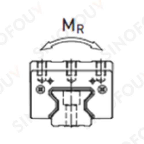
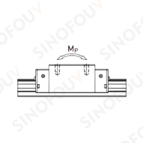
| H | H1 | N | W | B | B1 | C | L1 | L | K1 | K2 | G | Mxl | T | H2 | H3 | WR | HR | D | h | d | P | E | (mm) | C(kN) | C0(kN) | MR(kN-m) | MP(kN-m) | MY(kN-m) | Block(kg) | Rail(kg/m) | |
| QRH20CA | 34 | 5 | 12 | 44 | 32 | 6 | 36 | 57.5 | 86 | 15.8 | 6 | 5.3 | M5x8 | 8 | 8.3 | 8.3 | 20 | 21 | 9.5 | 8.5 | 6 | 30 | 20 | M5x20 | 26.3 | 38.9 | 0.591 | 0.453 | 0.453 | 0.4 | 2.76 |
| QRH25CA | 40 | 5.5 | 12.5 | 48 | 35 | 6.5 | 35 | 66 | 97.9 | 21.5 | 7.25 | 12 | M6x8 | 9.5 | 10.2 | 10 | 23 | 23.6 | 11 | 9 | 7 | 30 | 20 | M6x20 | 38.5 | 54.4 | 0.722 | 0.627 | 0.627 | 0.6 | 3.08 |
| QRH25HA | 40 | 5.5 | 12.5 | 48 | 35 | 6.5 | 50 | 81 | 112.9 | 21.5 | 7.25 | 12 | M6x8 | 9.5 | 10.2 | 10 | 23 | 23.6 | 11 | 9 | 7 | 30 | 20 | M6x20 | 44.7 | 65.3 | 0.867 | 0.907 | 0.907 | 0.74 | 3.08 |
| QRH30CA | 45 | 6 | 16 | 60 | 40 | 10 | 40 | 71 | 109.8 | 23.5 | 8 | 12 | M8x10 | 9.5 | 9.5 | 10.3 | 28 | 28 | 14 | 12 | 9 | 40 | 20 | M8x25 | 51.5 | 73 | 1.284 | 0.945 | 0.945 | 0.89 | 4.41 |
| QRH30HA | 45 | 6 | 16 | 60 | 40 | 10 | 60 | 93 | 131.8 | 24.5 | 8 | 12 | M8x10 | 9.5 | 9.5 | 10.3 | 28 | 28 | 14 | 12 | 9 | 40 | 20 | M8x25 | 64.7 | 95.8 | 1.685 | 1.63 | 1.63 | 1.15 | 4.41 |
| QRH35CA | 55 | 6.5 | 18 | 70 | 50 | 10 | 50 | 79 | 124 | 22.5 | 10 | 12 | M8x12 | 12 | 16 | 19.6 | 34 | 30.2 | 14 | 12 | 9 | 40 | 20 | M8x25 | 77 | 94.7 | 1.955 | 1.331 | 1.331 | 1.56 | 6.06 |
| QRH35HA | 55 | 6.5 | 18 | 70 | 50 | 10 | 72 | 106.5 | 151.5 | 25.25 | 10 | 12 | M8x12 | 12 | 16 | 19.6 | 34 | 30.2 | 14 | 12 | 9 | 40 | 20 | M8x25 | 95.7 | 126.3 | 2.606 | 2.335 | 2.335 | 2.04 | 6.06 |
| QRH45CA | 70 | 8 | 20.5 | 86 | 60 | 13 | 60 | 106 | 153.2 | 31 | 10 | 12.9 | M10x17 | 16 | 20 | 24 | 45 | 38 | 20 | 17 | 14 | 52.5 | 22.5 | M12x35 | 123.2 | 156.4 | 3.959 | 2.666 | 2.666 | 3.16 | 9.97 |
| QRH45HA | 70 | 8 | 20.5 | 86 | 60 | 13 | 80 | 139.8 | 187 | 37.9 | 10 | 12.9 | M10x17 | 16 | 20 | 24 | 45 | 38 | 20 | 17 | 14 | 52.5 | 22.5 | M12x35 | 150.8 | 208.6 | 5.718 | 5.086 | 5.086 | 4.1 | 9.97 |
| Model | Dimensions of Assembly(mm) | Dimensions of Block(mm) | Dimensions of Rail(mm) | Mounting Bolt for Rail | Basic Dynamic Load Rating | Basic Static Load Rating | Static Rated Moment | Weight | ||||||||||||||||||||
|---|---|---|---|---|---|---|---|---|---|---|---|---|---|---|---|---|---|---|---|---|---|---|---|---|---|---|---|---|
| H | H1 | N | W | B | B1 | C | L1 | L | G | Gn | Mxl | H2 | WR | HR | D | h | d | P | E | (mm) | C(kN) | C0(kN) | MR(N-m) | MP(N-m) | MY(N-m) | Block(kg) | Rail(kg/m) | |
| MGN2C | 3.2 | 0.7 | 2 | 6 | - | 3 | 4 | 9.5 | 12.5 | - | - | M1.4THRU | - | 2 | 2 | M1THRU | M1THRU | M1THRU | 8 | 4 | M1 | 0.22 | 0.4 | 0.42 | 0.63 | 0.63 | 0.001 | 0.03 |
| MGN3C | 4 | 1 | 2.5 | 8 | - | 4 | 3.5 | 7 | 11.3 | - | - | M1.6x1.3 | - | 3 | 2.6 | M1.6THRU | M1.6THRU | M1.6THRU | 10 | 5 | M1.6 | 0.29 | 0.44 | 0.7 | 0.5 | 0.5 | 0.001 | 0.05 |
| MGN3H | 4 | 1 | 2.5 | 8 | - | 4 | 5.5 | 11 | 15.3 | - | - | M2x1.3 | - | 3 | 2.6 | M1.6THRU | M1.6THRU | M1.6THRU | 10 | 5 | M1.6 | 0.39 | 0.68 | 1 | 1.3 | 1.3 | 0.002 | 0.05 |
| MGN7C | 8 | 1.5 | 5 | 17 | 12 | 2.5 | 8 | 13.5 | 22.5 | - | Ø1.2 | M2x2.5 | 1.5 | 7 | 4.8 | 4.2 | 2.3 | 2.4 | 15 | 5 | M2x6 | 0.98 | 1.24 | 4.7 | 2.84 | 2.84 | 0.01 | 0.22 |
| MGN7H | 8 | 1.5 | 5 | 17 | 12 | 2.5 | 13 | 21.8 | 30.8 | - | Ø1.2 | M2x2.5 | 1.5 | 7 | 4.8 | 4.2 | 2.3 | 2.4 | 15 | 5 | M2x6 | 1.37 | 1.96 | 7.64 | 4.8 | 4.8 | 0.015 | 0.22 |
| MGN9C | 10 | 2 | 5.5 | 20 | 15 | 2.5 | 10 | 18.9 | 28.9 | - | Ø1.4 | M3x3 | 1.8 | 9 | 6.5 | 6 | 3.5 | 3.5 | 20 | 7.5 | M3x8 | 1.86 | 2.55 | 11.76 | 7.35 | 7.35 | 0.016 | 0.38 |
| MGN9H | 10 | 2 | 5.5 | 20 | 15 | 2.5 | 16 | 29.9 | 39.9 | - | Ø1.4 | M3x3 | 1.8 | 9 | 6.5 | 6 | 3.5 | 3.5 | 20 | 7.5 | M3x8 | 2.55 | 4.02 | 19.6 | 18.62 | 18.62 | 0.026 | 0.38 |
| MGN12C | 13 | 3 | 7.5 | 27 | 20 | 3.5 | 15 | 21.7 | 34.7 | - | Ø2 | M3x3.5 | 2.5 | 12 | 8 | 6 | 4.5 | 3.5 | 25 | 10 | M3x8 | 2.84 | 3.92 | 25.48 | 13.72 | 13.72 | 0.034 | 0.65 |
| MGN12H | 13 | 3 | 7.5 | 27 | 20 | 3.5 | 20 | 32.4 | 45.4 | - | Ø2 | M3x3.5 | 2.5 | 12 | 8 | 6 | 4.5 | 3.5 | 25 | 10 | M3x8 | 3.72 | 5.88 | 38.22 | 36.26 | 36.26 | 0.054 | 0.65 |
| MGN15C | 16 | 4 | 8.5 | 32 | 25 | 3.5 | 20 | 26.7 | 42.1 | 4.5 | M3 | M3x4 | 3 | 15 | 10 | 6 | 4.5 | 3.5 | 40 | 15 | M3x10 | 4.61 | 5.59 | 45.08 | 21.56 | 21.56 | 0.059 | 1.06 |
| MGN15H | 16 | 4 | 8.5 | 32 | 25 | 3.5 | 25 | 43.4 | 58.8 | 4.5 | M3 | M3x4 | 3 | 15 | 10 | 6 | 4.5 | 3.5 | 40 | 15 | M3x10 | 6.37 | 9.11 | 73.5 | 57.82 | 57.82 | 0.092 | 1.06 |

 English
 русский
 中文
中文 info@s-fou.com